
The SHOCK Show #6: How do I determine full piezo property matrix for FEA?
Welcome to The SHOCK Show, Episode #5. So, I've been talking for the last three episodes about what causes non-symmetric resonance impedance and what to do about it. BUT, I didn't talk about why you should even care. Let me convince you that you should care in this episode.
Read on or watch the episode here: https://youtu.be/lhIBTmlEDIQ
What is the correct approach to FEA and experiments?
The whole reason why you want your material properties to be "correct" is to improve the accuracy of prediction of experimental behavior. The trap here is when we start to search for exact agreement, which can be an unending endeavor.
In almost all cases, FEA is best suited for understanding and verifying the function of a particular design rather than predicting precise displacement and impedance responses. This is because there is a lot more things different between experiments and FEA than just the differing piezo material properties from your experiment and simulation
So what's different?
The most drastic differences between experiments and FEA are:
- The effects that component interfaces play in loss and stiffness
- The unique behavior of high power operation, which results in nonlinearity and losses galore!
Now for the reason you are reading this article: Full piezo property matrix calculation
Everyone is asking me about how to input custom properties into FEA simulations despite not having all of the anisotropic material properties. So here is your desire:
Let's get started!
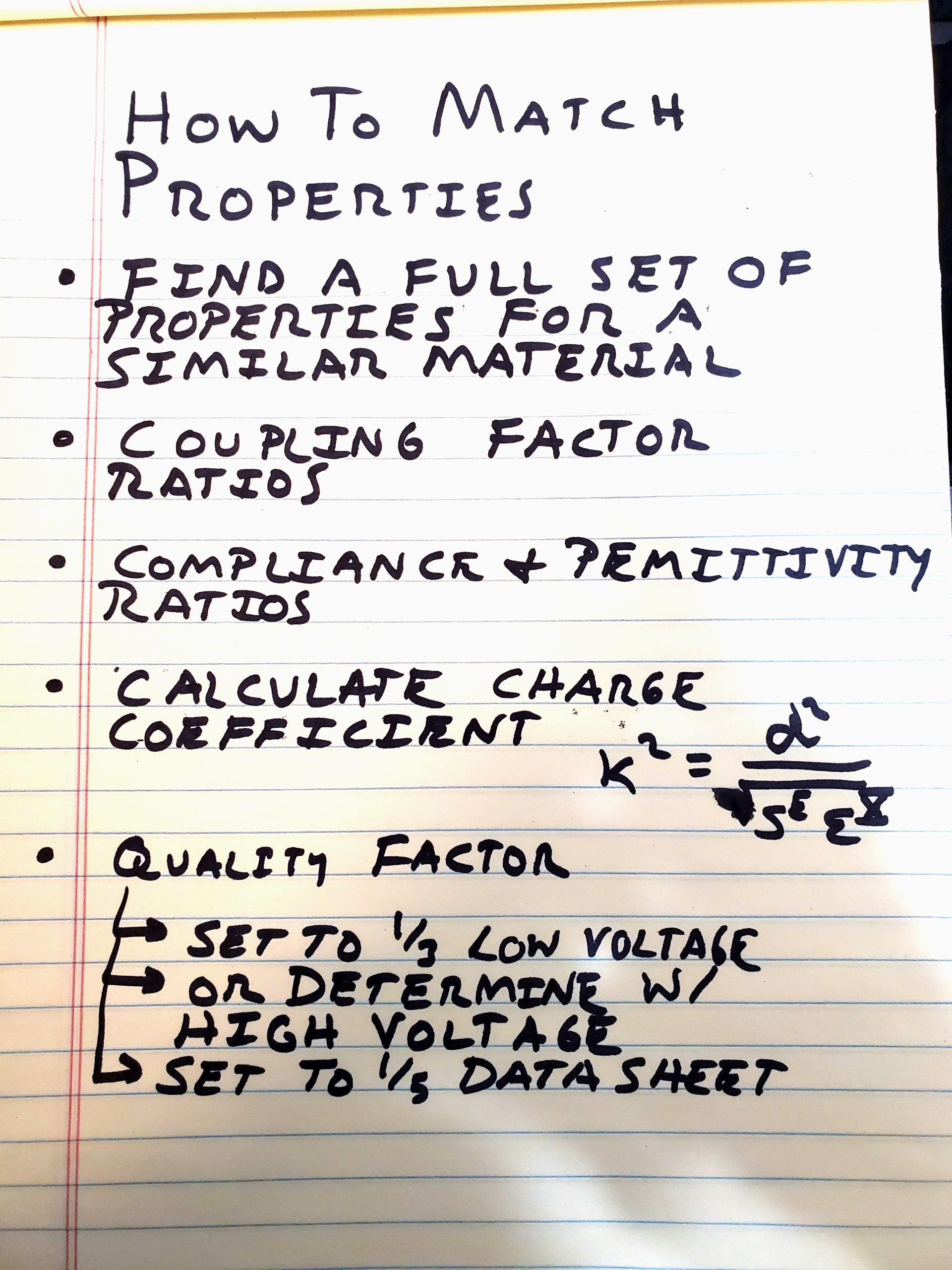
- Firstly, find a full set of material properties from a similar material. For example, if you are using a hard PZT, find a full matrix of material properties of another hard material
- Using data sheet values or values that you measure, compare ONE calculated coupling factor (k^2) from your material to the reference material. Find the ratio. Use this golden ratio to back calculate the coupling factors for the k15, k33, and k31 modes.
- Create ratios for permittivity and compliance. Then, back calculate all the missing values for your material
- Calculate the d15, d33, and d31 using the definition of the coupling factors and their relationship with the piezo charge coefficient, permittivity, and compliance. IE k^2=d^2/(compliance*permittivity) . Solve for d15, d33, and d31
- Now we will focus on the quality factor
- Measure your quality factor of your material experimentally. Divide this number by 3. If you are using the material data sheet Q-factor, divide it by 5. This will be close to the high power Q-factor
- It is much better to measure Q-factor from your assembly and measure Q factor in that way rather than just using crystal level Q-factor. You can then apply the 1/3 factor mentioned in the last bullet point.
- I recommend using a single loss factor for your material/assembly. Although piezo ceramics have loss anisotropy, for practical purposes you just need to consider one loss factor.