COMSOL Simulation of the Direct Piezoelectric Effect
COMSOL Simulation of the Direct Piezoelectric Effect
***I provide ultrasonic transducer simulation services for product development. Please learn more about my consulting here: https://www.ultrasonicadvisors.com/***
In this article, we are going to demonstrate the simulation of direct piezoelectric effect by using a FEA simulation program known as COMSOL. We will apply force to a piezoelectric element and from that force the piezoelectric element will produce voltage.
Equations Describing the Direct Piezoelectric Effect
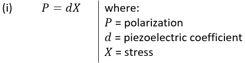
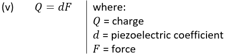
We will start with two equations. First is the piezoelectric equation, the relationship between polarization and stress:
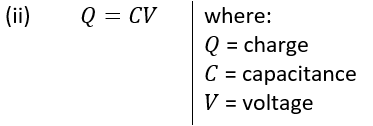
The second equation is the electrostatic equation of a capacitor:
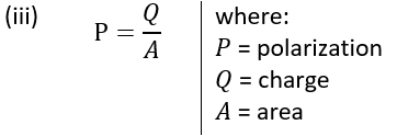
These two equations are important in understanding how an applied stress/force relates to a charge developed and will serve as the basis of our derivation. Since polarization (P) is essentially charge per area we have:
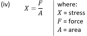
Also, since stress (X) is force per area we have:
Substituting Equation iii and iv to Equation i we have:

Simplifying the equation, we get:
With this equation, we can conclude that if we have a piezoelectric material and we apply a force to that material over a small area or a large area, we will get the same voltage – this is because the force is the area integral of applied stress.
However, in sensor applications, we typically measure voltage. There, we need to further derive to get an equation with respect to voltage.
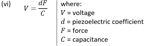
Substituting equation ii to Equation v we have:

Simplifying the equation, we get:
The capacitance here is determined by the permittivity of the material under free stress. So, we have the capacitance of the material using the formula:
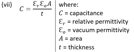
Substituting Equation vii to Equation vi we have our working equation in terms of voltage as:
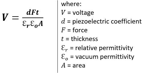
Based from the derived equation, we can say that as the area of the piezoelectric material increases, the voltage decreases.
Setting Up a Static Simulation in COMSOL Describing the Direct Piezoelectric Effect
Now let’s witness the direct piezoelectric effect by designing a simple cylinder in COMSOL and applying force and measuring voltage.
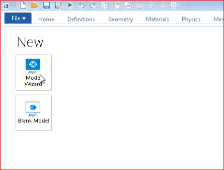
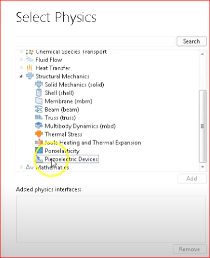
Firstly, we will go to model wizard in COMSOL. In our case select 3D then go to structural mechanics and select piezoelectric devices and add necessary physics for this simulation. We want to look at stationary results because we are doing a static simulation, so add stationary physics.
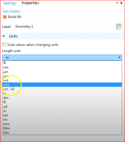
Change meters to millimeters because that’s primarily the scale we work in for piezoelectric devices.
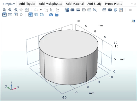
In order to add the piezoelectric element geometry, go to the geometry panel and build a cylinder.
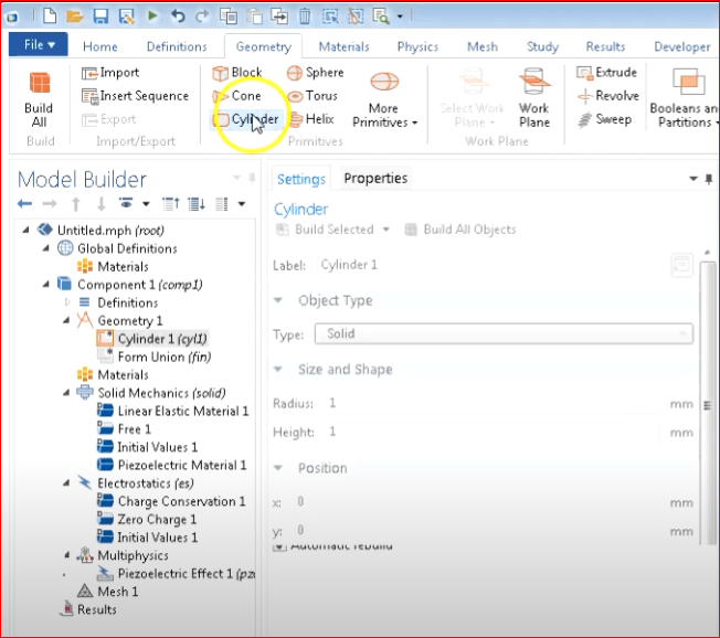
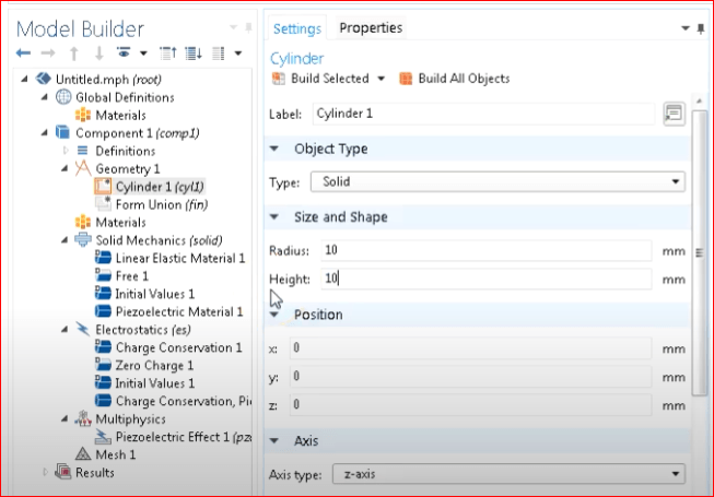
Set the cylinder radius and height 10mm and select Build All Objects.
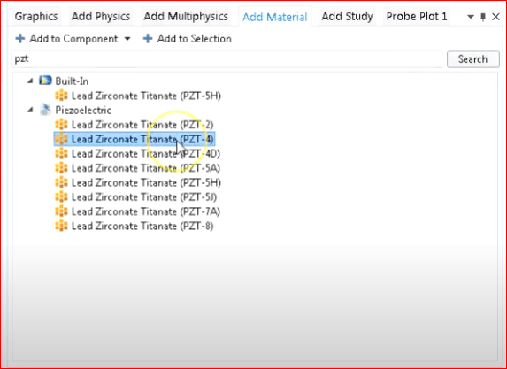
From the materials options, assign the PZT material by going to library and select PZT-4 which is the standard PZT.
Select Fixed Constraint in the Solid Mechanics to fix the material at the bottom.
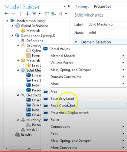
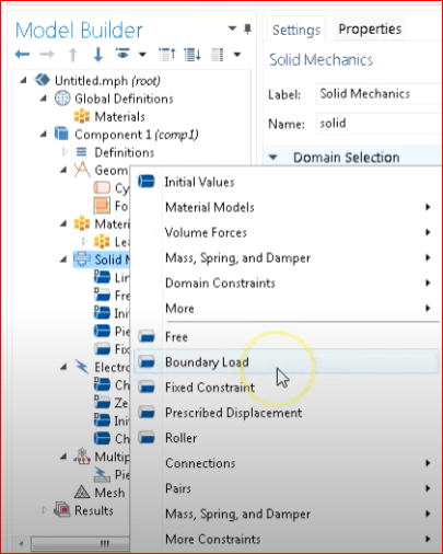
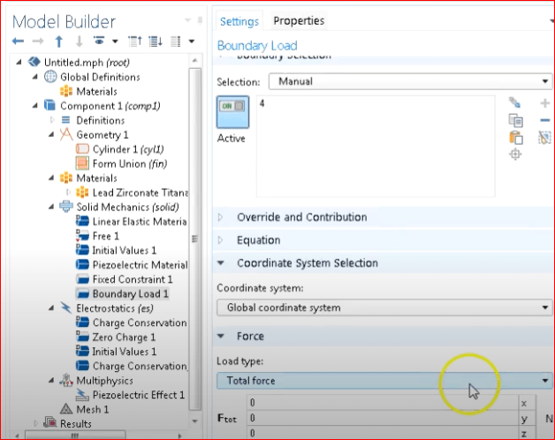
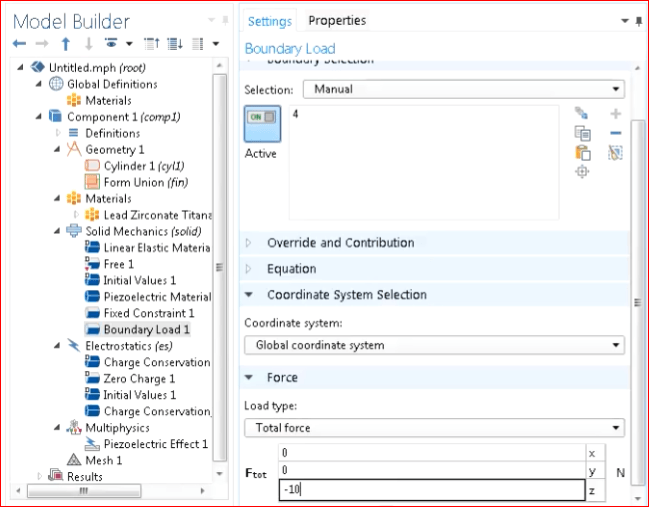
In order to apply force, under Solid Mechanics go to Boundary Load. Select Total Force as the Load Type and apply -10N to z-axis.
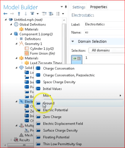
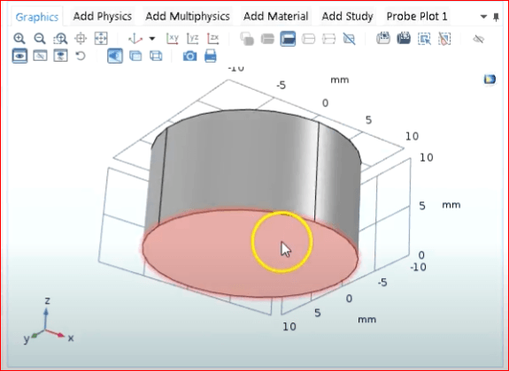
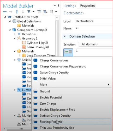
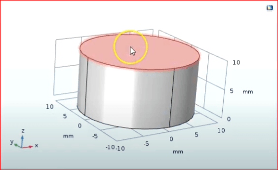
In order to measure voltage potential across the piezoelectric material, it is very important to note that when doing this in COMSOL, we need to specify one of the electrodes as "floating" and one as "ground".
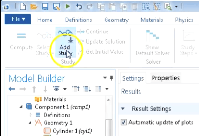
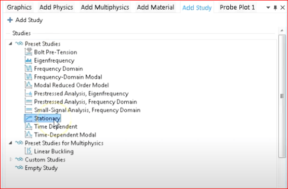
Select Add Study and Select Stationary.
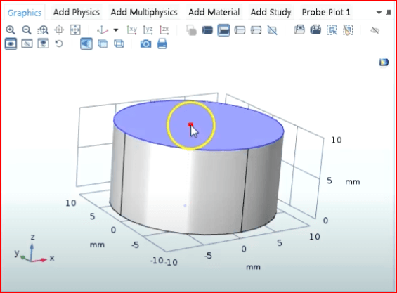
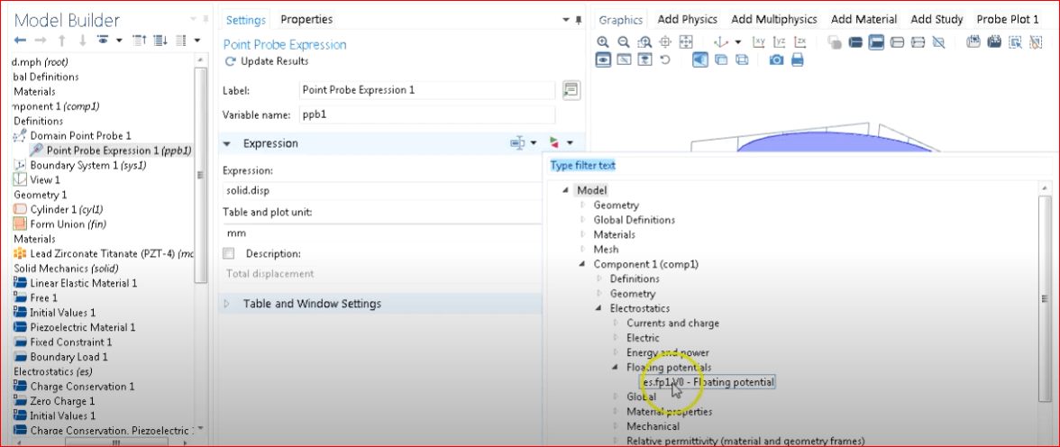
Under Definition, go to Probes, select Boundary Point Probe and specify the top of the piezoelectric material.
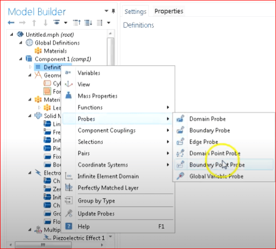
Under Point Probe Expression, specify Floating Potential.
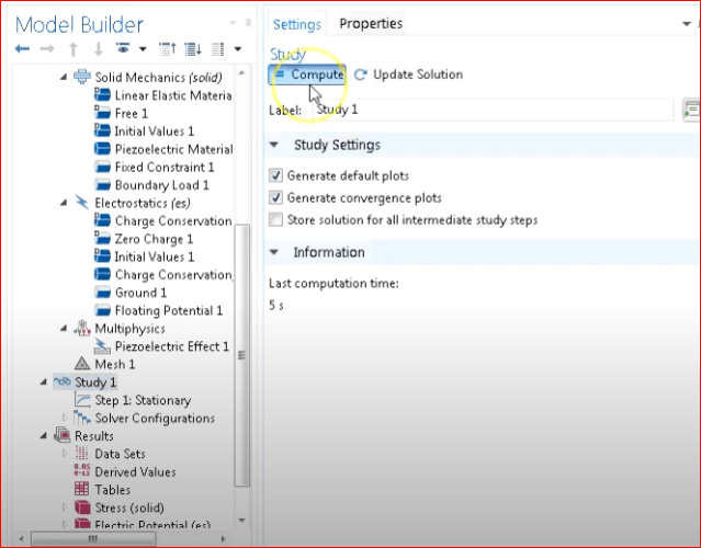
With all parameters set, we can now start the simulation by going to “Study” and clicking “Compute”.
Comparing Simulation Results
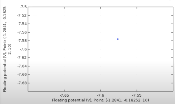
In order to find the voltage measurement, select Probe Plot in the Results. Here we can easily see that the floating potential is -7.58 V.
To verify our simulation, we will use our previously derived equation to solve the voltage and compare it with the value from our COMSOL simulation.
Using the formula, we substitute our values used in the simulation
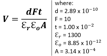
Substituting the values to the equation we get:
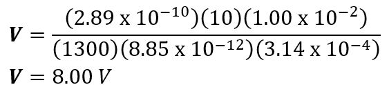
As we can see, there is a slight variation between our computed value and the value given by the COMSOL simulation. That difference is due to the constraint we put in the COMSOL simulation. When we constrained the bottom portion of the piezoelectric material, the material cannot get larger at the bottom as the force is applied. Nevertheless, we are able to verify that our simulation is correct.
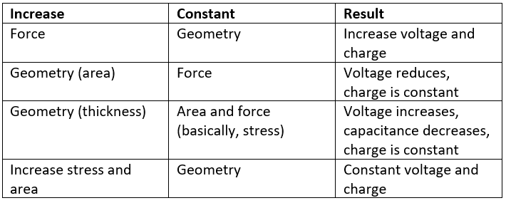
Here are some important relationships, assuming we increase one variable, keep constant another, and the following result: