
The SHOCK Show #3: Why is my resonance impedance not symmetric? P2
In this episode of the SHOCK show, I am going to discuss why we have nonsymmetric resonance response (impedance). The first reason (covered Episode #2) was that the coupling factor and the quality were low. The second reason covered here, still linear, is that multiple resonance modes can coincide.
Read on or watch the episode here: https://youtu.be/qcRxcV0p6Ug
And yes, I'll be talking through a mirror this episode!
Important definition
Also, FYI, the word for non-desirable resonance close to your operating resonance are called SPURIOUS MODES.
What is the deal with these coinciding modes?
There are a few causes for this effect of multiple modes. One of these causes, for a longitudinal transducer is that other modes such as bending modes and component modes can lie close to the operating frequency. This includes a screw/bolt resonance inside the clamped ends of the transducer (screw threads and bolt head). This might cause more than one resonance mode to lie on top of another one. This does depend on the resonance frequency associated with these modes. If the spurious modes lie near the resonance frequency, the resonance response will widen, not allowing you to use equivalent circuit analysis that is reserved for single mode analysis. Not to say that your driver will have trouble picking frequencies and also dump a significant energy into useless oscillation.
Defect free is the way to be... if only that were possible
The other reason modes can coexist at a similar frequency is due to defects. One example of this is imperfect symmetry. For example, if you are bonding a piezo disk to a passive disk and the two disks are not perfectly symmetric, additional closely spaced modes can occur. Epoxy and other interfaces can also have variable properties (bond strength and surface roughness and flatness) – these aspects also result in additional non-desirable resonance modes.
It's not your fault. You were born this way
Before working as a consultant, I thought all spurious modes close to the resonance frequency must be eliminated. That's because I had only worked on longitudal transducers. Bending modes especially are susceptible to spurious modes and many times you actually can't rid of them. At the end of this article, I'll tell you how to live your life in peace despite being surrounded with spurious modes.
Finally, an example!
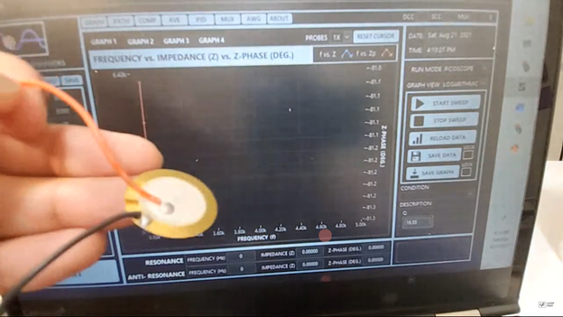
Let dig into an example with the impedance analysis of a piezo buzzer. Let’s do a frequency response from 3kHz to 5kHz. You can hear the response because it is in the audible range. New Paragraph
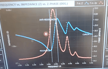
So, this transducer has spurious modes, but it doesn’t lie right on top of the resonance at 3.8 kHz. But there are additional modes at 4.3 and 4.5 kHz. These modes will be highly variable as they depend on bond conditions and concentricity.
If these modes landed close the resonance frequency, it would cause a distortion in the response, and typical analysis methods we use will not be valid, such as Q factor determination using the half power bandwidth.
So, are you going to tell me what to do if I have spurious modes or not?
In order to analyze a transducer that has a spurious at resonance, you can fit an equivalent circuit to the antiresonance response and perform analysis from there. Same goes if antiresonance has spurious modes. It’s not possible to determine the effective coupling factor in the presence of strong spurious modes, but it is possible when considering the equivalent circuit for the “pure” response either at resonance or antiresonance.
For most transducers, spurious activity is problematic and should be eliminated both by theoretical design via FEA model analysis. Harmonic analysis does not capture all modes so it has less utility for spurious mode analysis. The second way to eliminate this behavior is to optimize your assembly procedure or iterate different permissible physical dimensions of your transducers. This may help you to come up with a robust design.
If you are stuck with spurious remain calm. You have been given a parachute.
If you are stuck with a transducer with common spurious modes, you will need to supplement your impedance analysis with “ideal” system level analysis. This means measuring responses like displacement vs. frequency or sound pressure level vs frequency. Single point vibration analysis can play a unique role here as the location of the probing site will lead to sensitivity toward certain modes – this can help you to ignore the spurious mode and focus on the important mode of interest.