
The SHOCK Show #4: Why is my resonance impedance not symmetric? Nonlinearity P3
Welcome to The SHOCK Show, Episode #4. Today, I’m going to continue with the third reason why the resonance impedance response of a ultrasonic transducer can be non-symmetric. This reason has everything to do with non-linearity! Finally, we are getting to some juicy stuff.
Read on or watch the episode here: https://youtu.be/NppCKhcthPw
The two effects of nonlinearity
- Apparent linear properties become variable and dependent on amplitude of excitation
- Additional harmonics are generated
Treat the nonlinear as linear
The definition of linearity is that if you excite a system with a certain frequency, you will get that frequency and only that one back in the response. So, the linear method of describing a nonlinear behavior is by change in citing change in linear properties. That is, for example, change in the d33, compliance, and permittivity with excitation.
Let’s take a look at the implication of this.
Nonlinearity creates non-symmetric resonance impedance
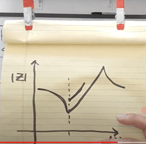
When a piezoelectric transducer oscillates near its resonance frequency, it’s level of oscillation increases until it peaks and them comes back down. Now, note that the properties of your transducer vary depending on the level oscillation.
Let’s analyze compliance, which increases with increased oscillation. As we are doing our frequency sweep, the oscillation increases and thus the compliance starts to increase. This causes the resonance frequency to retreat. The end effect of this is either a sharp dip and then a slow accent or a non-continuity in impedance.
For low voltage measurements, the first type is more common. However, because your impedance analyzer has a finite output impedance, it intrinsically limits the current delivered to your device, thus forcing the oscillation amplitude to remain relatively constant
Triangle waves? Just when you thought the worst was over
The second thing that nonlinearity does is inject additional harmonics, namely 3rd harmonic, into your response. This often results in your final current waveform having a more triangle wave-look than a sine wave. That being said, I have not seen that typical impedance analyzers can drive a transducer to this level of nonlinearity. A triangle wave has a lower RMS value than a sine wave for the same amplitude.
The harmonic solution
In order to do appropriate analysis, the FFT spectrum must be analyzed for first and third harmonics. The first harmonic should be used for impedance characterization, but information regarding average DC power and the amplitude of the third harmonic should be recorded.
Avoiding nonlinearity?
Nonlinearity is part of the ultrasonic transducer game. However, controlling excitation levels and performing FFT help us to come to terms with the peculiarities of nonlinear behavior.